
Click here to jump directly to the cheat sheet.
This page contains guidelines for large-scale 3D printing. This means that, in general, these dimensions and offsets work. With different materials, different geometries, or different printing strategies, the right settings/offsets might deviate from the ones mentioned on this page.
How to determine layer width?
The first step in the design process is to determine the layer width. Sometimes the layer width is not very critical but a lot of times it is. You can encounter these scenarios:
- You need a specific thickness somewhere in your design
When you need a wall thickness of 12 mm somewhere, that will be a determining factor in the layer width. Depending on the geometry (and the ability to create a continuous path), you might need one or two beads thick at this specific spot. If you need two beads thick, calculate the single bead thickness via the pointers in the section 'how much should two beads overlap'. - You need to post-process (mill) the part after printing
Usually, milling away 5 mm should be enough to get rid of the layer lines and end up with a smooth surface. If you want to keep a wall that is still strong enough, make sure you leave 10 mm of material. This means that the total thickness of 15 mm is required.
If you need another thickness or want to mill away more (or less), you can calculate the layer width for milling with the formula below:
Layerwidth (LW) = Thickness required after milling - Thickness to be milled away
Note: please note that when slicing with a 45 degree slicing angle, you usually need to apply a factor of the square root of 2 with the thickness & width.
How to determine which nozzle diameter to use?
Choosing the right nozzle is critical for a good quality. Read this article about nozzle size selection if you want to learn what nozzle you need for what bead dimension:
How to Choose the right nozzle size?
How to determine layer height?
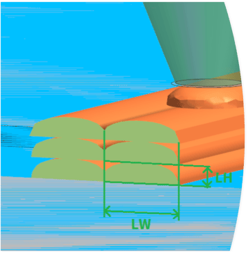
The layer height is less prone to strict rules and guidelines. Layer heights between 2 and 5 mm should generally work for most layer widths as long as the layer height is not more than 50% of the layer width (so a 4 mm layer height does not work with a 6 mm layer width).
General guidelines that some material suppliers recommend are using a 1:4 ratio between layer height and layer width (so a 6 mm layer width would work optimally with a 1.5 mm layer height).
For bigger layer widths a ratio between 1:4 and 1:8 generally works better and for smaller layer widths a ratio between 1:2 and 1:4 generally works better.

(left) Detailed: 1xLW = 8xLH; (middle) Regular: 1xLW = 4xLH; (right) Coarse: 1xLW = 2xLH
If your layer height is too small, the amount of material that is pushed out the nozzle is too much to deposit. If this is the case, you will see a distinguishing ‘wrinkling’ pattern in your bead like the image below.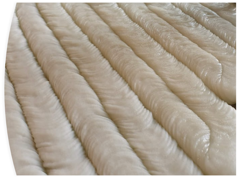
How do I need to design any sharp corners?
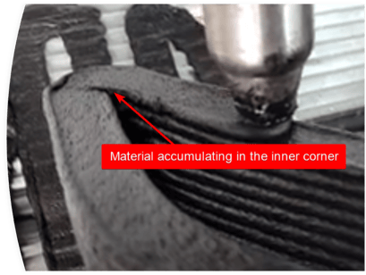
If inner corners are too sharp, material might accumulate there which can trigger a snowball effect that leads to unwanted defects in your print or worst case, in a print failure.
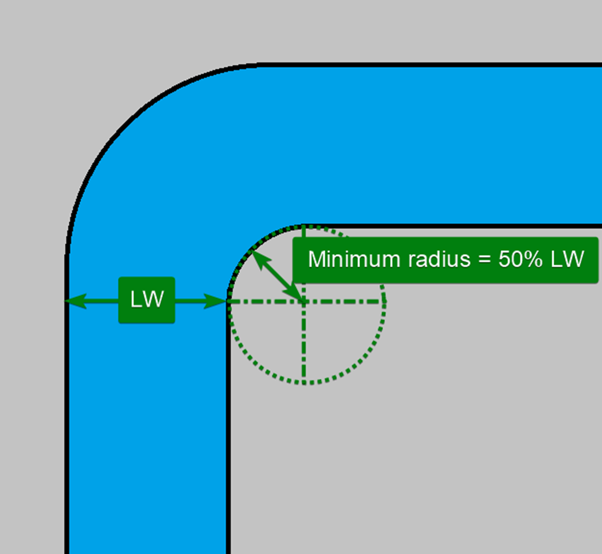
In general, for inner radiuses, keep a minimal radius of 50% of the layer width.
Minimum inner radius (IR) = 50% x Layer Width (LW)
In general, for outer radiuses, keep a minimal radius of 150% of the layer width.
Minimum outer radius (OR) = 150% x Layer Width (LW)
How much should two beads overlap?
In most designs, beads need to touch or overlap. Either to achieve more strength, have more material to mill away, or to be able to design a continuous toolpath.
In the design phase, it is important to make sure that beads like the example below overlap.
Overlap
During tests, it was found that beads have the optimal adhesion vs. strength when they overlap between 5 and 10% of the layer width. In general, using an overlap of 7.5% should be sufficient.
Overlap (OL) = 7.5% x Layer witdh (+/- 33%)
Design offset
In the example below of a holding fixture, a layer width of 12 mm was used. The part does not need to be milled afterward and it was calculated that 12 mm was enough, if the part had a solid middle part where the two beads meet.
In the design, a closed geometry was designed and the outer walls where the beads should meet (see the image below) were given an offset of two times the layer width minus 7.5% overlap.
Design offset (DO) = 2 x Layer Width (LW) - Overlap (OL)

Determine the layer width due to a fixed width in your design
If your layer width is limited due to a certain feature that needs a specific thickness and you need a double bead at this spot, the formula below can determine your layer width. Use the other layer widths from this article to determine the optimal height and inner/outer minimum radius.
Layer Width = Required thickness 2 beads (DO) / (2 - 0.075*)

* if you need more or less overlap, you can adapt this number from 0.05 to 0.1.
Cheatsheet - Design offsets & layer geometry
all dimensions in the table below are in mm. All the average values are displayed.
The layer height can be tweaked from a factor 0.5 to factor 2.
The design offset can deviate +/- 1.3% from the displayed value
The overlap can deviate +/- 33% from the displayed value.
| 3,0 | 0,8 | 5,8 | 0,2 | 1,5 | 4,5 |
| 4,0 | 1,0 | 7,7 | 0,3 | 2,0 | 6,0 |
| 5,0 | 1,3 | 9,6 | 0,4 | 2,5 | 7,5 |
| 6,0 | 1,5 | 11,6 | 0,5 | 3,0 | 9,0 |
| 7,0 | 1,8 | 13,5 | 0,5 | 3,5 | 10,5 |
| 8,0 | 2,0 | 15,4 | 0,6 | 4,0 | 12,0 |
| 9,0 | 2,3 | 17,3 | 0,7 | 4,5 | 13,5 |
| 10,0 | 2,5 | 19,3 | 0,8 | 5,0 | 15,0 |
| 11,0 | 2,8 | 21,2 | 0,8 | 5,5 | 16,5 |
| 12,0 | 3,0 | 23,1 | 0,9 | 6,0 | 18,0 |
| 13,0 | 3,3 | 25,0 | 1,0 | 6,5 | 19,5 |
| 14,0 | 3,5 | 27,0 | 1,1 | 7,0 | 21,0 |
| 15,0 | 3,8 | 28,9 | 1,1 | 7,5 | 22,5 |
| 16,0 | 4,0 | 30,8 | 1,2 | 8,0 | 24,0 |
| 17,0 | 4,3 | 32,7 | 1,3 | 8,5 | 25,5 |
| 18,0 | 4,5 | 34,7 | 1,4 | 9,0 | 27,0 |
| 19,0 | 4,8 | 36,6 | 1,4 | 9,5 | 28,5 |
| 20,0 | 5,0 | 38,5 | 1,5 | 10,0 | 30,0 |
| 21,0 | 5,3 | 40,4 | 1,6 | 10,5 | 31,5 |
| 22,0 | 5,5 | 42,4 | 1,7 | 11,0 | 33,0 |
| 23,0 | 5,8 | 44,3 | 1,7 | 11,5 | 34,5 |
| 24,0 | 6,0 | 46,2 | 1,8 | 12,0 | 36,0 |
| 25,0 | 6,3 | 48,1 | 1,9 | 12,5 | 37,5 |
| 26,0 | 6,5 | 50,1 | 2,0 | 13,0 | 39,0 |
| 27,0 | 6,8 | 52,0 | 2,0 | 13,5 | 40,5 |
| 28,0 | 7,0 | 53,9 | 2,1 | 14,0 | 42,0 |
| 29,0 | 7,3 | 55,8 | 2,2 | 14,5 | 43,5 |
| 30,0 | 7,5 | 57,8 | 2,3 | 15,0 | 45,0 |